
Indoor Unit Error Display:
| Error Codes | LED Status |
|---|---|
| E0 | EEPROM parameter error |
| E1 | Indoor / outdoor units communication protection |
| E2 | Zero-crossing signal error |
| E3 | Indoor fan speed out of control |
| E5 | Open or short circuit of outdoor temperature sensor or outdoor unit EEPROM parameter error |
| E6 | Open or short circuit of room or evaporator temperature sensor |
| E7 | Outdoor fan speed out of control |
| P0 | IBM malfunction or IGBT over-strong current protection |
| P1 | Over voltage or too low voltage protection |
| P2 | Temperature protection of compressor top. |
| P4 | Inverter compressor drive error |
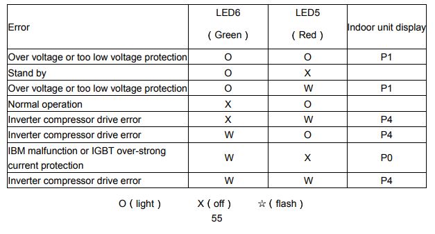
Outdoor unit error display:
On the outdoor PCB, there are two LED lights. One is green, the other is red. You can judge what the error is through the status of the two lights.
Indoor Unit Display: P1
LED 6 (Green) Light, LED 5 (RED) Light: Over voltage or too lows or too voltage protection
Indoor Unit Display: P2
LED 6 (Green) Light, LED 5 (RED) Flash: Over voltage or too lows or too voltage protection
Indoor Unit Display: P4
LED 6 (Green) Off, LED 5 (RED) Flash: Inverter compressor drive error
Indoor Unit Display: P4
LED 6 (Green) Flash, LED 5 (RED) Light: Inverter compressor drive error
Indoor Unit Display: P4
LED 6 (Green) Flash, LED 5 (RED) Flash: Inverter compressor drive error
Indoor Unit Display: P0
LED 6 (Green) Flash, LED 5 (RED) Off: IBM malfuntion or IGBT over-strong current protection
Indoor Unit Display: Stand by
LED 6 (Green) Light, LED 5 (RED) Off: Stand by
Troubleshooting
Malfunctions: Unit does not start
Cause:
- Power cut
- Unit may have become Unplugged
- Fuse may have blown
- Battery in Remote controller may have been exhausted
- The time you have set with timer is incorrect
What should be done:
- Wait for power to be restored
- Check that plug is securely in wall receptacle
- Replace the fuse
- Replace the battery
- Wait or cancel timer setting
Malfunctions: Unit not cooling or heating (Cooling/ heating models only) room very well while air flowing out from the air cond tioner
Cause:
- Inappropriate temperature setting
- Air filter is blocked
- Doors or Windows are open
- Air inlet or outlet of indoor or outdoor unit has been blocked
- Compressor 3 minutes protection has been activated
What should be done:
- Set temperature correctly. For detailed method please refer to ”Using remote control” section
- Clean the air filter
- Close the doors or windows
- Clear obstructions away first, then restart the unit
- Wait
Malfunctions: The unit starts and stops frequently
Cause:
- There’s too much or too little refrigerant in the system
- Incompressible gas or moisture has entered the system.
- The compressor is broken
- The voltage is too high or too low
What should be done:
- Check for leaks and recharge the system with refrigerant.
- Evacuate and recharge the system with refrigerant
- Replace the compressor
- Install a manostat to regulate the voltage
Issue: Both the indoor unit and outdoor unit make noises
Possible Causes:
- Low hissing sound during operation: This is normal and is caused by refrigerant gas flowing through both indoor and outdoor units.
- Low hissing sound when the system starts, has just stopped running, or is defrosting: This noise is normal and is caused by the refrigerant gas stopping or changing direction.
- Squeaking sound: Normal expansion and contraction of plastic and metal parts caused by temperature changes during operation can cause squeaking noises.
Diagnosis and Solution
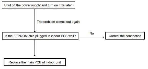
EEPROM parameter error diagnosis and solution
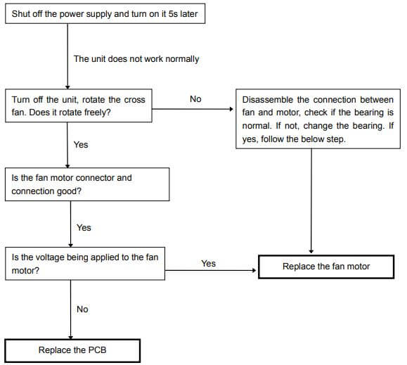
Fan speed has been out of control diagnosis
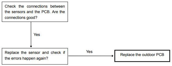
Open or short circuit of temperature sensor diagnosis and solution
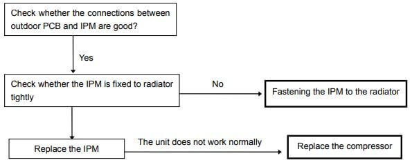
IGBT over-strong current protection diagnosis and solution
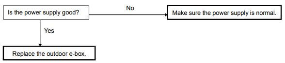
Over voltage or too low voltage protection diagnosis and solution
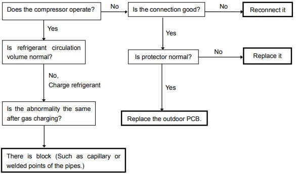
High temperature protection of compressor top diagnosis and solution
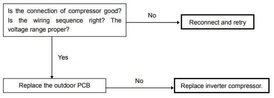
Inverter compressor drive error diagnosis and solution
Zero crossing detection error
This is alarm signal when the main chip can’t detect over-zero signal. When such failure occurs, the main control board must have fault.
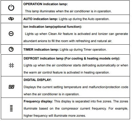
Display function
Icon explanation on indoor display board.
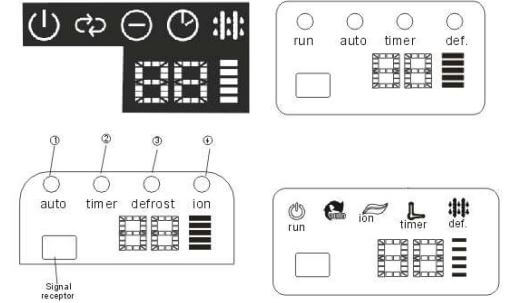
OPERATION indication lamp: This lamp illuminates when the air conditioner is in operation.
AUTO indication lamp: Lights up during the Auto operation.
Ion indication lamp (optional function): Lights up when Clean Air feature is activated and Ionizer can generate abundant anions to fill the room with refreshing and natural air.
TIMER indication lamp: Lights up during Timer operation.
DEFROST indication lamp (For cooling & heating models only): Lights up when the air conditioner starts defrosting automatically or when the warm air control feature is activated in heating operation.
DIGITAL DISPLAY: Displays the current setting temperature and malfunction/protection code when the air conditioner is in operation.
Frequency display: This display is separated into five zones. The zones illuminate based on the compressor current frequency. For example, higher frequency will illuminate more zones.
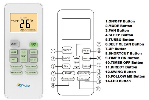
Senville Air Conditioner Remote Control Symbol Meaning
Senville AURA Series Air Conditioner Manual PDF
Senville AURA Series Multi-Zone Air Conditioner Manual PDF
Senville LETO Series Air Conditioner Manual PDF
Source: senville.com
Comments
Post a Comment