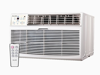
Scandic and Tropic Series
When below list for identification of error code occurs, please turn off air conditioner and disconnect power, and then contact the qualified professionals for service.

| Error Code | Troubleshooting |
|---|---|
| E0 | Indoor unit EEPROM parameter error |
| E1 | Indoor / outdoor units communication error |
| E2 | Zero-crossing signal detection error |
| E3 | Indoor fan speed has been out of control |
| E4 | Indoor room temperature sensor T1 open circuit or short circuit |
| E5 | Evaporator coil temperature sensor T2 open circuit or short circuit |
| EC | Refrigerant leakage detection |
| F1 | Outdoor temperature sensor T4 open circuit or short circuit |
| F2 | Condenser coil temperature sensor T3 open circuit or short circuit |
| F3 | Compressor discharge temperature sensor T5 open circuit or short circuit |
| F4 | Outdoor unit EEPROM parameter error |
| F5 | Outdoor fan speed has been out of control |
| P0 | IPM malfunction or IGBT over-strong current protection |
| P1 | Over voltage or over low voltage protection |
| P2 | High temperature protection of compressor top diagnosis and solution |
| P4 | Inverter compressor drive error |
Troubleshooting
Before calling for service, review this list. It may save your time and expense. This list includes common occurrences that are not the result of defective workman-ship or materials in this appliance.
| Problem | Solution |
|---|---|
| Air conditioner does not start | Wall plug disconnected. Push plug firmly into wall outlet. |
| House fuse blown or circuit breaker tripped. Replace fuse with time delay type or reset circuit breaker. | |
| Plug Current Device Tripped. Press the RESET button. | |
| Power is OFF. Turn power ON. | |
| Air from unit does not feel cold enough | Room temperature below 62 F(17 C ). Cooling may not occur until room temperature O O rises above 62 F(17 C). |
| Temperature sensing behind air filter element touching cold coil. Keep it from the cold coil. | |
| Set to a Lower temperature. | |
| Compressor stopped when changing modes. Wait for 3 minutes after set to the COOL mode. | |
| Air conditioner cooling, but room is too warm- ice forming on cooling coil behind decorative front. | Outdoor temperature below 64 F(18 C). To defrost the coil, set FAN ONLY mode. |
| Air filter may be dirty. Clean filter. Refer to Care and Cleaning section. To defrost, set to FAN ONLY mode. | |
| Thermostat set too cold for night-time cooling. To defrost the coil, set to FAN ONLY mode. Then, set temperature to a Higher setting. | |
| Air conditioner cooling, but room is too warm- NO ice forming on cooling coil behind decorative front. | Dirty air filter- air restricted. Clean air filter. Refer to Care and Cleaning section. |
| Temperature is set too High, set temperature to a Lower setting. | |
| Air directional louvers positioned improperly. Position louvers for better air distribution. | |
| Front of units is blocked by drapes, blinds, furniture, etc. - restricts air distribution. Clear blockage in front of unit. | |
| Doors, windows, registers, etc. Open- cold air escapes. Close doors, windows, registers. | |
| Unit recently turned on in hot room. Allow additional time to remove Stored heat from walls, ceiling, floor and furniture. | |
| Air conditioner turns on and off rapidly | Dirty air filter- air restricted. Clean air filter. |
| Outside temperature extremely hot. Set FAN speed to a Higher setting to bring air past cooling coils more frequently | |
| Noise when unit is cooling | Air movement sound. This is normal . If too loud, set to a slower FAN setting |
| Window vibration - poor installation. Refer to installation instructions or check with installer. | |
| Water dripping INSIDE when unit is cooling. | Improper installation. Tilt air conditioner slightly to the outside to allow water drainage. Refer to installation instructions - check with installer. |
| Water dripping OUTSIDE when unit is cooling. | Unit removing large quantity of moisture from humid room. This is normal during excessively humid days. |
| Remote Sensing Deactivating Prematurely (some models) | Remote control not located within range. Place remote control within 20 feet & 180 , radius of the front of the unit. |
| Remote control signal obstructed. Remove obstruction. | |
| Room too cold | Set temperature too low. Increase set temperature. |
Diagnosis and Solution
EEPROM parameter error diagnosis and solution (E0/F4)
Malfunction decision conditions: Indoor or outdoor PCB main chip does not receive feedback from EEPROM chip.
Supposed causes:
- Installation mistake
- PCB faulty
Indoor / outdoor unit’s communication diagnosis and solution (E1)
Malfunction decision conditions: Indoor unit does not receive the feedback from outdoor unit during 110 seconds and this condition happens four times continuously.
Supposed causes:
- Wiring mistake
- Indoor or outdoor PCB faulty
Zero crossing detection error diagnosis and solution (E2)
Malfunction decision conditions: When PCB does not receive zero crossing signal feedback for 4 minutes or the zero crossing signal time interval is abnormal.
Supposed causes:
- Connection mistake
- PCB faulty
Fan speed has been out of control diagnosis and solution (E3)
Malfunction decision conditions: When indoor fan speed keeps too low (300RPM) for certain time, the unit will stop and the LED will display the failure.
Supposed causes:
- Wiring mistake
- Fan ass’y faulty
- Fan motor faulty
- PCB faulty
Open circuit or short circuit of temperature sensor diagnosis and solution (E5)
Malfunction decision conditions: If the sampling voltage is lower than 0.06V or higher than 4.94V, the LED will display the failure.
Supposed causes:
- Wiring mistake
- Sensor faulty
Refrigerant Leakage Detection diagnosis and solution (EC)
Malfunction decision conditions: Define the evaporator coil temp.T2 of the compressor just starts running as Tcool. In the beginning 5 minutes after the compressor starts up, if T2 < Tcool 28.4o F(-2o C) does not keep continuous 4 seconds and this situation happens 3 times, the display area will show “EC” and AC will turn off.
Supposed causes:
- T2 sensor faulty
- Indoor PCB faulty
- System problems, such as leakage or blocking.
IPM malfunction or IGBT over-strong current protection diagnosis and solution (P0)
Malfunction decision conditions: When the voltage signal that IPM send to compressor drive chip is abnormal, the display LED will show “P0” and AC will turn off.
Supposed causes: Wiring mistake; IPM malfunction; Outdoor fan ass’y faulty Compressor malfunction; Outdoor PCB faulty
Over voltage or too low voltage protection diagnosis and solution (P1)
Malfunction decision conditions: An abnormal voltage rise or drop is detected by checking the specified voltage detection circuit.
Supposed causes:
- Power supply problems.
- System leakage or block
High temperature protection of compressor top diagnosis and solution (P2)
Malfunction decision conditions: If the sampling voltage is not 5V, the LED will display the failure.
Supposed causes:
- Power supply problems.
- System leakage or block
Inverter compressor drive error diagnosis and solution (P4)
Malfunction decision conditions: An abnormal inverter compressor drive is detected by a special detection circuit, including communication signal detection, voltage detection, compressor rotation speed signal detection and so on.
Supposed causes: Wiring mistake; IPM malfunction; Outdoor fan ass’y faulty Compressor malfunction; Outdoor PCB faulty
Comments
Post a Comment