
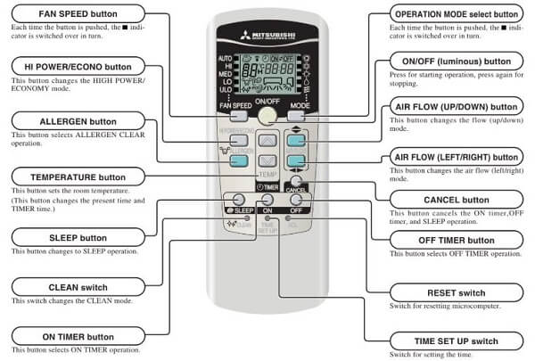
- Split Systems
- VRF Inverter Multi-System
1.Split Systems
Whether a failure exists or not on the indoor unit and outdoor unit can be know by the contents of remote controller eroor code, indoor/outdoor unit green LED (power pilot lamp and microcomputer normality pilot lamp) or red LED (check pilot lamp).
a.Check Indicator Table;
Indoor Unit Side
| Error Codes | Cause |
|---|---|
| E1 | When multiple remote controllers are used for control, the power supply to some indoor units is OFF. |
| Indoor unit PCB fault | |
| The remote controller wire Y is open. The remote controller wires X and Y are reversely connected. Noise is penetrating the remote control lines. The remote controller or indoor control PCB is faulty. | |
| E5 | Indoor / outdoor transmission error. |
| Outdoor unit control PCB is faulty when the power is turned on, or the inverter parts are faulty. | |
| Outdoor unit microcomputer failure. | |
| E6 | Indoor unit heat exchanger thermistor failure |
| E7 | Indoor unit return air thermistor failure |
| E8 | Heating overload (indoor heat exchanger temperature is abnormally high) and indoor heat exchanger thermistor is faulty. |
| E9 | The float SW operates (with FS only). Drain up kit wiring fault. |
| E10 | When multi-unit control by remote controller is performed, the number of units is over (more than 17 units). Two remote controller are provided for one controller is performed. |
| E16 | Fan motor is faulty (FDTA 501, 601 type, FDKN type) |
| E28 | Remote controller thermistor failure |
Outdoor Unit Side
| Error Codes | Cause |
|---|---|
| E32 | Wiring is open or reversal phase (FDCA 301~601 type) |
| E33 | Inverter primary side current is abnormal. (FDCVA151~251 type) |
| Abnormal current cut of compressor (FDCA 301~601 type) | |
| E34 | 52C secondary side L3-phase wiring is open. (FDCA 301~601 type) |
| E35 | Outdoor heat exchanger temperature is high or outdoor heat exchanger thermistor is faulty |
| E36 | Discharge temperature abnormality. |
| E37 | Outdoor unit heat exchanger thermistor failure |
| E38 | Outdoor air temperature thermistor failure |
| E39 | Discharge pipe thermistor failure |
| E40 | 63H1 operation (FDCA 301~601 type) |
| E42 | Current (Abnormalities in a compressor over current) |
| E47 | Inverter Over-voltage Trouble. (FDCVA 151~251 type) |
| E48 | DC fan motor abnormal. (FDCVA 151~251 type) |
| E52 | 52C abnormal. (FDCA 301~601 type) |
| E56 | Power transistor thermistor is faulty or disconnection or connector connections are poor. |
| E57 | Insufficient refrigerant. |
| E59 | Compressor startup error (FDCVA 151~251 type) |
| E60 | Compressor loader position detection error. (FDCVA 151~251 type) |
b.Display Sequence of Error, Inspection Display Lamp;
| Error Codes | Error Detail |
|---|---|
| Indoor Unit Side | |
| E1 | Transmission error of remote controller indoor unit. Timing of error detection: After 1 or more communications of the indoor unit with the remote controller following power on, transmission errors cause an interruption for 2 minutes. |
| E5 | Transmission error between indoor/outdoor units. Timing of error detection: After communications with the outdoor unit 1 or more times, communications are abnormal continuously for 2 minutes. |
| E6 | Broken wire of heat exchanger thermistor. Timing of error detection: When an input temperature of –50°C or lower is measured by the heat exchanger thermistor is measured for 5 seconds or longer within 60 minutes after the first detection. |
| E7 | Broken wire of indoor unit return air thermistor. Timing of error detection: When an input temperature of –50°C or lower is measured by the return air thermistor is measured for 5 seconds or longer within 60 minutes after the first detection. |
| E9 | Drain error (float switch motion). Timing of error detection: Normally, 30 seconds after the power is turned ON |
| E10 | The number of connected indoor units exceeds the connection limit. Timing of error detection: Normally after the power is turned ON (during communications). |
| Outdoor Unit Side | |
| E38 | Broken wire of outdoor air temperature thermistor. Timing of error detection: When a thermistor input temperature of –30°C or lower is measured for 5 seconds or longer 3 times within 40 (60) minutes after the 1st detection between 2 minutes and 2 minutes 20 seconds after compressor operation starts. |
| E37 | Broken wire of heat exchanger thermister. Timing of error detection: When a thermistor input temperature of –30°C or lower is measured for 5 seconds or longer 3 times within 40 (60) minutes after the 1st detection between 2 minutes and 2 minutes 20 seconds after compressor operation starts. |
| E39 | Broken wire of discharge pipe thermistor. Timing of error detection: When a thermistor input temperature of –10°C or lower is measured for 5 seconds or longer 3 times within 40 (60) minutes after the 1st detection between 10 minutes and 10 minutes 20 seconds (between 2 minutes and 2 minutes 20 seconds) after compressor operation starts. |
| E55 | Broken wire of power transistor thermistor. Timing of error detection: When the under-dome thermistor input temperature of –10°C is measured for 5 seconds or longer 3 times within 40 minutes after the 1st detection between 10 minutes and 10 minutes 20 seconds after compressor operation starts. |
Inverter Wall Mounted Type Room AC Error Codes
Error code, stop code table (Assignment of error codes and stop codes is done in common for all models.)
2.VRF Inverter Multi System (KX4 series and KX6 series):
| Remote Control Error Codes | Description of Fault |
|---|---|
| E1 | Remote controller communication error. Possible Cause: Anomalous communication circuit between remote controller and indoor unit, Noise. |
| E2 | Duplicated indoor unit addressing more than 49 units connected. Possible Cause: Number of connected indoor units exceeds the limitation, Duplicated indoor unit address, Indoor PCB anomaly. |
| E3 | Outdoor unit signal line error. Possible Cause: Power is not suppied to outdoor unit, Unmatch of pairing between indoor and outdoor units, Indoor PCB anomaly, Outdoor control PCB anomaly, Missing local wiring. |
| E5 | Communication error during operation. Possible Cause: Unit address No. setting error, Remote control wires broken, Poor connection/ disconnection of remote controller wires, Indoor control PCB anomaly, Noise. |
| E6 | Indoor heat exchanger temp. sensor anomaly (Thi-R). Possible Cause: Sensor anomaly, Poor connection, Indoor control PCB anomaly. |
| E7 | Indoor return air temp. sensor anomaly (Thi-A). Possible Cause: Sensor anomaly, Poor connection, Indoor control PCB anomaly. |
| E9 | Drain trouble. Possible Cause: Blocked drain, Drain pump anomaly, Float switch anomaly, Indoor contyrol PCB anomaly. |
| E10 | Excessive number of indoor units by controlling one renote controller. Possible Cause: Excessive number of indoor units connected (more than 17 units), Remote controller anomaly. |
| E11 | Address setting error (setting with remote controller). Possible Cause: When plural indoor units are connected, do not use remote controller address setting method. |
| E12 | Address setting error by mixed setting method. Possible Cause: The atomatic setting and manual setting mixed in the address setting method for indoor units. |
| E16 | Indoor fan motor anomaly. Possible Cause: Fan motor anomaly, Poor connection, Indoor PCB anomaly. |
| E18 | Address setting error of master and slave indoor remote controller. Possible Cause: Remote controller SW address setting error of master and slave indoor units. |
| E19 | Indoor unit operation check, drain motor check mode anomaly. Possible Cause: Mistake in SW7-1 setting due to forgetting to turn OFF SW7-1 after indoor operation check finished. |
| E20 | Indoor fan motor rotationtion speed anomaly (FDT, FDTC, FDK, FDTW). Possible Cause: DC fan motor revolution speed anomaly, Indoor power (control) PCB anomaly, Foreign material at rotational area of fan motor. |
| E21 | FDT Limit switch is not activated. Possible Cause: Limit switch on the panel anomaly, Anomalous mounting position of gille, Connector CNV loose. |
| E22 | Wrong connection with Outdoor unit. Possible Cause: Unmatched pairing of indoor and outdoor unit, Indoor control PCB anomaly, Outdoor control PCB anomaly. |
| E28 | Remote controller temp. sensor anomaly (Thc). Possible Cause: Remote controller temp. sensor anomaly, Poor connection, Remote controller PCB anomaly. |
| E30 | Unmatch connection of indoor and outdoor unit. Possible Cause: Indoor control PCB anomaly, Outdoor control PCB anomaly. |
| E31 | Duplicated outdoor unit address No.. Possible Cause: Mistake in the address setting of outdoor units, More than 129 indoor units connected, No setting of Master/Slave setting switch for combination use. |
| E32 | Open L3 phase on power supply at primary side. Possible Cause: Anomalous power supply at primary side, Outdoor control PCB anomaly. |
| E36 | 1.Discharge pipe temp. sensor anomaly, Outdoor control PCB anomaly, Short circuit of airflow, Insufficient airflow volume, Insufficient amount of refrigerant, SV1, 2 (liquid refrigerant by pass valve) anomaly. 2. Liquid flooding anomaly. Overcharging of refrigerant, Superheat control anomaly, Circuit of liquid refrigerant by pass anomaly, Discharge pipe temp. sensor anomaly, EEV indoor anomaly. |
| E37 | Outdoor heat exchanger temp. sensor (Tho-R) and subcooling coil temp. sensor (Tho-SC, -H) anomaly. Possible Cause: Broken sensor harness or the internal wire of sensing section, Poor connection, Outdoor contron PCB anomaly. |
| E38 | Outdoor air temp. sensor anomaly (Tho-A). Possible Cause: Broken sensor harness or the internal wire of sensing section, Poor connection, Outdoor contron PCB anomaly. |
| E39 | Discharge pipe temp. sensor anomaly (Tho-D1, D2). Possible Cause: Broken sensor harness or the internal wire of sensing section, Poor connection, Outdoor contron PCB anomaly. |
| E40 | High pressure anomaly (63H1-1,2 activated). Possible Cause: Disconnection of high pressure switch connector, High pressure sensor anomaly, High pressure switch anomaly, Short circuit of airflow at condenser, Close service valve. |
| E41 | Power transistor overheat. Possible Cause: Power transistor anomaly, Power transistor temp. sensor anomaly, Improperly fixing of power transistor to radiator fin, Inverter PCB anomaly, Outdoor fan motor anomaly, Cooling fan motor for inverter anomaly, Inadequate installation space of outdoor unit. |
| E51 | Power transistor overheat. Possible Cause: Power transistor anomaly, Power transistor temp. sensor anomaly, Improperly fixing of power transistor to radiator fin, Inverter PCB anomaly, Outdoor fan motor anomaly, Cooling fan motor for inverter anomaly, Inadequate installation space of outdoor unit. |
| E42 | Current cut (CM1, CM2). Possible Cause: Compressor anomaly, Leakage of refrigerant, Power transistor module anomaly, Anomalous power supply for inverter PCB, Outdoor fan motor anomaly. |
| E43 | Excessive number of indoor units connected, excessive total capacity. Possible Cause: Mistake in setting of indoor/outdoor unit addresses, Mistake in signal wire connection. |
| E45 | Communication error between inverter PCB and outdoor control PCB. Possible Cause: Signal wire anomaly, Outdoor control PCB anomaly, Inverter PCB (INV1,2) anomaly, Rush current prevention resistor anomaly. |
| E46 | Mixed address setting methods conexistent in same network. Possible Cause: Mistake in the address setting, Mistake in the connection of signal wire. |
| E48 | Outdoor DC fan motor anomaly. Possible Cause: Outdoor fan motor anomaly, Poor connection, Inverter PCB anomaly, Outdoor control PCB anomaly. |
| E49 | Low pressure anomaly. Possible Cause: Low pressure sensor anomaly, Service valves closed, EEV anomaly (EEV closed), Insufficient refrigerant amount, Clogging at EEV or strainer. |
| E53 | Suction pipe temp. sensor anomaly (Tho-S). Possible Cause: Broken sensor harness or the internal wire of sensing section, Poor connection, Outdoor contron PCB anomaly. |
| E54 | High pressure sensor anomaly (PSH)/ Low pressure sensoe anomaly (PSL). Possible Cause: Broken sensor harness, Disconnection of sensor, Sensor (PSH, PSL) anomaly, Outdoor control PCB anomaly, Anomalous installation condition, Insufficient airflow volume, Excessive or insufficient refrigerant amount. |
| E55 | Under-dome temp. sensor anomaly (Tho-C1, C2). Possible Cause: Broken sensor harness or the internal wire of sensing section, Poor connection, Outdoor contron PCB anomaly. |
| E56 | Power transistor temp. senser anomaly (Tho-P1, P2). Possible Cause: Broken sensor harness or the internal wire of sensing section, Poor connection, Outdoor contron PCB anomaly. |
| E58 | Anomalous compressor by loss of synchronism. Possible Cause: Insufficient time elapsed after the power supplied before compressor startup, Startup compressor without crankcase heater ON, Compressor anomaly. |
| E59 | Compressor startup failure (CM1, CM2). Possible Cause: Anomalous voltage of power supply, Anomalous components for refrigerant circuit, Inverter PCB anomaly, Loose connection of connector or cable, Compressor anomaly (Motor or bearing) |
| E60 | Rotor position detection failure (CM1, CM2). Possible Cause: Compressor anomaly, Inverter PCB anomaly, Anomaly of power supply. |
| E61 | Communication error between the master unit and slave units. Possible Cause: Signal wire anomaly, Outdoor control PCB anomaly, Inverter PCB (INV1,2) anomaly, Rush current prevention resistor anomaly. |
| E63 | Emergency stop. Possible Cause: Factors for emergency stop. |
| E75 | Central control communication error. Possible Cause: Poor connection, faulty controller. |
Mitsubishi Heavy Industries AC Self-diagnosis Table
When this air conditioner performs an emergency stop, the reason why the emergency stop occurred is displayed by the flashing of display lights. If the air conditioner is operated using the remote control 3 minutes or more after the emergency stop, the trouble display stops and the air conditioner resumes operation.
Mitsubishi heavy industries air conditioner timer light flashing:
| RUN light | TIMER light | Outdoor unit LED | Wired remote control display | Description of trouble | Cause | Display (flashing) condition |
|---|---|---|---|---|---|---|
| 1 time flash | ON | — | — | Heat exchanger sensor 1 error | Broken heat exchanger sensor 1 wire, poor connector connection | When a heat exchanger sensor 1 wire disconnection is detected while operation is stopped. (If a temperature of –28ºC or lower is detected for 15 seconds, it is judged that the wire is disconnected.) (Not displayed during operation.) |
| 2 time flash | ON | — | — | Room temperature sensor error | Broken room temperature sensor wire, poor connector connection | When a room temperature sensor wire disconnection is detected while operation is stopped. (If a temperature of –45ºC or lower is detected for 15 seconds, it is judged that the wire is disconnected.) (Not displayed during operation.) |
| 3 time flash | ON | — | — | Heat exchanger sensor 3 error | Broken heat exchanger sensor 3 wire, poor connector connection | When a heat exchanger sensor wire 3 disconnection is detected while operation is stopped. (If a temperature of –28ºC or lower is detected for 15 seconds, it is judged that the wire is disconnected.) (Not displayed during operation.) |
| 6 time flash | ON | — | E16 | Indoor fan motor error | Defective fan motor, poor connector connection | When conditions for turning the indoor unit’s fan motor on exist during air conditioner operation, an indoor unit fan motor speed of 300 rpm or lower is measured for 30 seconds or longer. (The air conditioner stops.) |
| Keeps flashing | 1 time flash | 8 time flash | E38 | Outdoor air temperature sensor error | Broken outdoor air temp. sensor wire, poor connector connection | When an outdoor temperature sensor wire disconnection is detected while the power is turned on or after the outdoor unit’s speed has continued at 0rps or higher for 2 minutes. (If a temperature of –55ºC or lower is detected for 20 seconds, it is judged that wire is disconnected.) (The compressor is stopped.) |
| Keeps flashing | 2 time flash | 8 time flash | E37 | Outdoor heat exchanger sensor erro | Broken heat exchanger sensor wire, poor connector connection | When a heat exchanger sensor wire disconnection is detected while the power is turned on or after the outdoor unit’s speed has continued at 0rps or higher for 2 minutes. (If a temperature of –55ºC or lower is detected for 20 seconds, it is judged that wire is disconnected.) (The compressor is stopped.) |
| Keeps flashing | 4 time flash | 8 time flash | E39 | Discharge pipe sensor error | Broken discharge pipe sensor wire, poor connector connection | When a discharge pipe sensor wire disconnection is detected after the outdoor unit’s speed has continued at 0rps or higher for 10 minutes. (If a temperature of –25ºC or lower is detected for 20 seconds, it is judged that wire is disconnected.) (The compressor is stopped.) |
| ON | 1 time flash | 1 time flash | E42 | Current Cut | Compressor locking, open phase on compressor output, shortcircuit on power transistor, closed service valve | The inverter output current (compressor motor current) exceeds the set value during compressor start. (The air conditioner stops.) |
| ON | 2 time flash | 2 time flash | E59 | Trouble of outdoor unit | Broken compressor wire. Compressor blockage. | When there is an emergency stop caused by trouble in the outdoor unit, or the input current value is found to be lower than the set value. (The air conditioner stops.) |
| ON | 3 time flash | 3 time flash | E58 | Current safe stop | Overload operation. Overcharge. Compressor locking. | When the inverter command speed is lower than the set value and the current safe has operated. (the compressor stops) |
| ON | 4 time flash | 1 time flash | E51 | Powe rtransistor error | Broken power transistor | When the power transistor is judged breakdown while compressor starts. (The compressor is stopped.) |
| ON | 5 time flash | 5 time flash | E36 | Over heat of ON compressor | Gas shortage, defective discharge pipe sensor, closed service valve | When the value of the discharge pipe sensor exceeds the set value. (The air conditioner stops.) |
| ON | 6 time flash | 6 time flash | E3-E5 | Error of signal transmission | Defective power supply, Broken signal wire, defective in/outdoor unit boards. | When there is no signal between the indoor unit’s board and outdoor unit’s board for 10 seconds or longer (when the power is turned on), or when there is no signal for 7 minute 35 seconds or longer (during operation)(the compressor is stopped). |
| ON | 7 time flash | ON | E48 | Outdoor fan motor error | Defective fan motor, poor connector connection | When the outdoor unit’s fan motor speed continues for 30 seconds or longer at 75 rpm or lower. (3 times) (The air conditioner stops.) |
| ON | Keeps flashing | 2 time flash | E35 | Cooling high pressure protecton | Overload operation, overcharge. Broken outdoor heat exchange sensor wire. Closed service valve. | When the value of the outdoor heat exchanger sensor exceeds the set value. |
| 2 time flash | 2 time flash | 7 time flash | E60 | Rotor lock | Defective compressor. Open phase on compressor. Defective outdoor unit boards. | If the compressor motor’s magnetic pole positions cannot be correctly detected when the compressor starts. (The air conditioner stops.) |
| 5 time flash | ON | 2 time flash | E47 | Active filter ON voltage error | Defective active filter | When the wrong voltage connected for the power supply. When the outdoor control PCB is faulty |
| — | — | — | E1 | Error of wired remote control wiring | Broken wired remote control wire, defective indoor unit boards | The wired remote control wire Y is open. The wired remote control wires X and Y are reversely connected. Noise is penetrating the wired remote control lines. The wired remote control or indoor control PCB is faulty. (The communications circuit is faulty.) |
Error code, stop code table (Assignment of error codes and stop codes is done in common for all models.)
| RUN light (10's digit) | TIMER light (1's digit) | Stop code or Error code | Error content-Cause-Occurrence conditions |
|---|---|---|---|
| OFF | OFF | 0 | Normal |
| OFF | 5 time flash | 05 | Can not receive signals for 35 seconds (if communications have recovered). Power supply is faulty. Power supply cables and signal lines are improperly wired. Indoor or outdoor unit circuit boards are faulty. When 35 seconds passes without communications signals from either the outdoor unit or the indoor unit being detected correctly. |
| 3 time flash | 5 time flash | 35 | Cooling high pressure control. Cooling overload operation. Outdoor unit fan speed drops. Outdoor heat exchanger sensor is short circuit. When the outdoor heat exchanger sensor's value exceeds the set value. |
| 3 time flash | 6 time flash | 36 | Compressor overheat (115˚C). Refrigerant is insufficient. Discharge pipe sensor is faulty. Service valve is closed. When the discharge pipe sensor's value exceeds the set value. |
| 3 time flash | 7 time flash | 37 | Outdoor heat exchanger sensor is abnormal. Outdoor heat exchanger sensor wire is disconnected. Connector connections are poor. When a temperature of –55˚C or lower is sensed continuously for 20 seconds while the power is turned on or after the outdoor unit's speed has continued at 0rps or higher for 2 minutes (the compressor stops). |
| 3 time flash | 8 time flash | 38 | Outdoor air temperature sensor is abnormal. Outdoor air temperature sensor wire is disconnected. Connector connections are poor. When a temperature of –55˚C or lower is sensed continuously for 20 seconds while the power is turned on or after the outdoor unit's speed has continued at 0rps or higher for 2 minutes (the compressor stops). |
| 3 time flash | 9 time flash | 39 | Discharge pipe sensor is abnormal (anomalous stop). Discharge pipe sensor wire is disconnected. Connector connections are poor. When a temperature of –25˚C or lower is sensed continuously for 20 seconds after the outdoor unit's speed has continued at 0rps or higher for 10 minutes (the compressor stops). |
| 4 time flash | 2 time flash | 42 | Current cut. Compressor lock. Compressor wiring short circuit. Compressor output is open phase. Outdoor unit's circuit board is faulty. Service valve is closed. Electronic expansion valve is faulty. Compressor is faulty. Compressor start fails 42 times in succession and the reason for the final failure is current cut. |
| 4 time flash | 7 time flash | 47 | Active filter voltage error. Defective active filter. When the wrong voltage connected for the power supply. When the outdoor control PCB is faulty |
| 4 time flash | 8 time flash | 48 | Outdoor unit's fan motor is abnormal. Outdoor fan motor is faulty. Connector connections are poor. Outdoor unit's circuit board is faulty. When a fan speed of 75 rpm or lower continues for 30 seconds or longer. |
| 5 time flash | 1 time flash | 51 | Short circuit in the power transistor (high side) Current cut circuit breakdown. Outdoor unit's circuit board is faulty. Power transistor is damaged. When it is judged that the power transistor was damaged at the time the compressor started. |
| 5 time flash | 7 time flash | 57 | Refrigeration cycle system protective control. Service valve is closed. Refrigerant is insufficient. When refrigeration cycle system protective control operates. |
| 5 time flash | 8 time flash | 58 | Current safe. Refrigerant is overcharge. Compressor lock. Overload operation. When there is a current safe stop during operation. |
| 5 time flash | 9 time flash | 59 | Compressor wiring is unconnection Voltage drop Low speed protective control. Compressor wiring is disconnected. Power transistor is damaged. Power supply construction is defective. Outdoor unit's circuit board is faulty. When the current is 1A or less at the time the compressor started. When the power supply voltage drops during operation. When the outdoor unit's speed is lower than 26 rps for 60 minutes. |
| 6 time flash | OFF | 60 | Rotor lock. Compressor is faulty. Compressor output is open phase. Electronic expansion valve is faulty. Overload operation. Outdoor unit's circuit board is faulty. After the compressor starts, when the compressor stops due to rotor lock. |
| 6 time flash | 1 time flash | 61 | Connection lines between the indoor and outdoor units are faulty. Connection lines are faulty. Indoor or outdoor unit circuit boards are faulty. When 10 seconds passes after the power is turned on without communications signals from the indoor or outdoor unit being detected correctly. |
| 6 time flash | 2 time flash | 62 | Serial transmission error. Indoor or outdoor unit circuit boards are faulty. Noise is causing faulty operation. When 7 minute 35 seconds passes without communications signals from either the outdoor unit or the indoor unit being detected correctly. |
| 8 time flash | OFF | 80 | Indoor unit's fan motor is abnormal. Indoor fan motor is faulty. Connector connections are poor. Indoor unit's circuit board is faulty. When the indoor unit's fan motor is detected to be running at 300 rpm or lower speed with the fan motor in the ON condition while the air conditioner is running. |
| 8 time flash | 2 time flash | 82 | Indoor heat exchanger sensor is abnormal (anomalous stop). Indoor heat exchanger sensor wire is disconnected. Connector connections are poor. When a temperature of –28˚C or lower is sensed continuously for 40 minutes during heating operation. (the compressor stops). |
| 8 time flash | 4 time flash | 84 | Anti-condensation control. High humidity condition. Humidity sensor is faulty. Anti-condensation prevention control is operating. |
| 8 time flash | 5 time flash | 85 | Anti-frost control. Indoor unit fan speed drops. Indoor heat exchanger sensor is broken wire. When the anti-frost control operates and the compressor stops during cooling operation. |
| 8 time flash | 6 time flash | 86 | Heating high pressure control. Heating overload operation. Indoor unit fan speed drops. Indoor heat exchanger sensor is short circuit. When high pressure control operates during heating operation and the compressor stops. |
Comments
Post a Comment