The repair personnel shall collect the error information as more as possible for careful study and list those electric or system parts that might cause the error. Then, the repair personnel shall be able to identify the specific cause of error and find out the problem parts.

List of Unit Errors-List of Error Display on Wired Controller:
| Error Codes | Solution |
|---|---|
| E1 | Compressorhigh-pressureprotection. The high pressure protection value is 4.2MPa. When it is detected three times successively that a compressor is under high pressure, this compressor will be stopped. In this case, error code E1 will be displayed and the run indicator will blink. |
| E2 | Indoor antifreeze protection. When it is detected for 10 minutes successively that Tevap. is ≤-2℃ (varying with indoor unit), the antifreeze protection will be activated, in which case the outdoor unit will immediately shut off the indoor electronic expansion valve and the capacity will be set to “0”. |
| E3 | Compressor low-pressure protection. When the low pressure reaches the protection value (absolute pressure: 0.15MPa), the low pressure switch will be cut off, in which case the low pressure protection will be displayed. |
| E4 | Compressor exhaust temperature protection. When the exhaust temperature (Texhau.) is equal to and higher than 113℃, the compressor will be stopped. Upon the first occurrence of exhaust protection, the error code E4 will be displayed. When the exhaust temperature is lower than TR℃, the compressor will resume to operation after it has been stopped for 3 minutes. The compressor can resume to operation for the first two times. But if this occurs three times successively in 1 hour, the unit must be disconnected from power supply before it can restarted |
| E5 | Frequency converter over current protection. The drive board of variable frequency compressor is incurred to error. For details on the error message, please refer to the Display Code on Digital Tube of Outdoor Unit. |
| E6 | Communication error. The mainboard of indoor unit or the wired control is incurred to communication error with outdoor unit. The indoor unit incurred to communication error will be stopped and display the error code. |
| E7 | Mode conflict. The run mode of the unit that is started later is inconsistent to the mode that is started earlier. Only the cooling and dry mode has possible mode conflict against the heat mode. For fan mode, there is no mode conflict against the cooling, dry or heat mode. In case mode conflict occurs, the indoor unit with mode conflict will display E7 and be stopped. |
| E9 | Water-full protection. When water full is detected for 8 seconds successively, the system will enter into water-full protection state, in which case the wired controller will display E9 and give out alarm. In case of water-full protection under each mode, the other loads of the indoor unit will be stopped, except that the water pump will remain working and give out alarm. In this case, the outdoor unit shall adjust the capacity output accordingly. |
| F0 | Indoor ambient temperature sensor error. The indoor unit incurred to sensor error will display error code and be stopped. |
| F1 | Indoor coil inlet temperature sensor error. The indoor unit incurred to sensor error will display error code and be stopped. |
| F2 | Indoor coil middle temperature sensor error. The indoor unit incurred to sensor error will display error code and be stopped. |
| F3 | Outdoor coil inlet temperature sensor error. The indoor unit incurred to sensor error will display error code and be stopped. |
| F4 | Outdoor ambient temperature sensor error. Test for 30 seconds successively to check if the temperature sensor is disconnected. If yes, alarm will be sent; otherwise no processing will be made. If the controller of outdoor unit detects failure of outdoor sensor under open circuit, short circuit and excess of test value, the outdoor unit will execute the following default actions, that is, the error message will be sent to each indoor unit and the error code will be displayed via error indicator or wired controller. When the outdoor ambient temperature is lower than -5℃, the disconnection failure of outdoor inlet, middle and exit sensors in shield room will be processed as under -30℃. |
| F7 | Outdoor defrost temperature sensor error. Test for 30 seconds successively to check if the temperature sensor is disconnected. If yes, alarm will be sent; otherwise no processing will be made. If the controller of outdoor unit detects failure of outdoor sensor under open circuit, short circuit and excess of test value, the outdoor unit will execute the following default actions, that is, the error message will be sent to each indoor unit and the error code will be displayed via error indicator or wired controller. When the outdoor ambient temperature is lower than -5℃, the disconnection failure of outdoor inlet, middle and exit sensors in shield room will be processed as under -30℃. |
| F9 | Exhaust temperature sensor error. Test for 30 seconds successively to check if the temperature sensor is disconnected. If yes, alarm will be sent; otherwise no processing will be made. If the controller of outdoor unit detects failure of outdoor sensor under open circuit, short circuit and excess of test value, the outdoor unit will execute the following default actions, that is, the error message will be sent to each indoor unit and the error code will be displayed via error indicator or wired controller. When the outdoor ambient temperature is lower than -5℃, the disconnection failure of outdoor inlet, middle and exit sensors in shield room will be processed as under -30℃. |
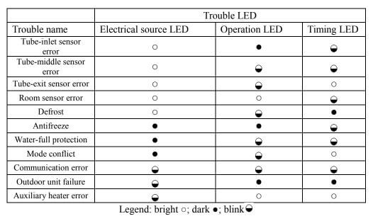
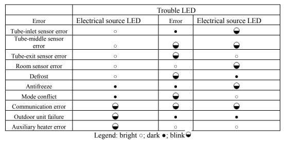
Trouble Display of Indoor Unit
- E1: High-pressure protection
- E2: Prevention against low temperature
- E3: Low-pressure protection
- E4: Exhaust overtemperature
- E5: Overcurrent Protector
- E6: Communication error
- E9: Water-full protection
- F0: Indoor ambient temperature sensor error
- F1: Indoor tube-inlet sensor error
- F2: Indoor tube-middle sensor error
- F3: Indoor tube-exit sensor error
- F4: Outdoor ambient temperature sensor error
- F5: Outdoor tube-inlet sensor error
- F6: Outdoor tube-middle sensor error
- F7: Outdoor tube-exit sensor error
- F8: Error with exhaust temperature sensor 1 (fixed-frequency)
- F9: Error with exhaust temperature sensor 2 (digital)
- FA: Error with oil temperature sensor 1 (fixed-frequency)
- Fb: Error with oil temperature sensor 2 (digital)
- Fc: High-pressure valve error
- Fd: Low-pressure valve error
- EH: Thermal relay error
Warning mark code:
- HO: Main wire controller mark
- SL: Slave wire controller mark
- CH: Mark of confilcting with the effective main wire controller
- CL: Mark of eliminating main wire
- No: No main indoor unit
- CC: Romote shield
- EE: Key locked
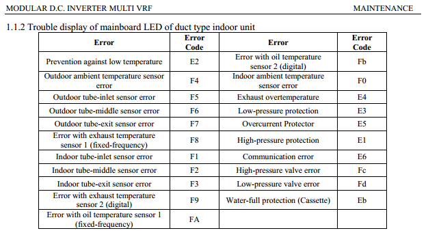
Modular D.C. Inverter Multi VRF Error Codes
Trouble display of mainboard LED of duct type indoor unit
- F4: Outdoor ambient temperature sensor error
- F5: Outdoor tube-inlet sensor error
- F6: Outdoor tube-middle sensor error
- F7: Outdoor tube-exit sensor error
- F8: Error with exhaust temperature sensor 1 (fixed-frequency)
- F1: Indoor tube-inlet sensor error
- F2: Indoor tube-middle sensor error
- F3: Indoor tube-exit sensor error
- F9: Error with exhaust temperature sensor 2 (digital)
- FA: Error with oil temperature sensor 1 (fixed-frequency)
- Fb: Error with oil temperature sensor 2 (digital)
- F0: Indoor ambient temperature sensor error
- E4: Exhaust overtemperature
- E3: Low-pressure protection
- E5: Overcurrent Protector
- E1: High-pressure protection
- E6: Communication error
- Fc: High-pressure valve error
- Fd: Low-pressure valve error
- Eb: Water-full protection (Cassette)
Common Troubleshooting
Check the following items before contacting for repair.
Phenomenon: The unit doesn’t run.
Reason-Measure:
- Without power supply. Connect to power supply.
- Voltage is too low. Check if the voltage is within rating range.
- Broken fuse or breaker trips off. Replace fuse or connect breaker.
- Insufficient energy of remote controller. Replace new battery.
- Remote controller is out of control scope. Control scope is within 8m.
Phenomenon: Abnormal cooling or heating
Reason-Measure:
- Air intake or outlet of indoor or outdoor unit is blocked. Remove obstruction.
- Improper temperature setting. Adjust setting at wireless remote controller or wired controller.
- Fan speed is set too low. Adjust setting at wireless remote controller or wired controller.
- Wind direction is not correct. Adjust setting at wireless remote controller or wired controller.
- Door or windows are opened. Close the door or windows.
- Direct sunshine. Draw curtain or louver.
- Too many heat resources in the room. Reduce heat resources.
- Filter is blocked for dirt. Clean the filter.
Comments
Post a Comment