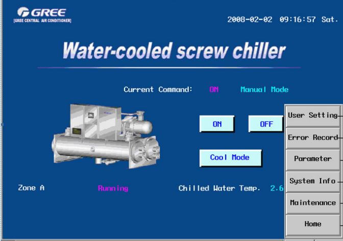
Gree Water-Cooled Screw Chiller

Error Display: high pressure of compressor
Name: high pressure protection
Source of Error Signal: high pressure switch
Description: When the high temperature of system exceeds the setting value, the high pressure protection occurs and the corresponding malfunction LED lights while the compressor stops immediately. The malfunction information is shown on the wired controller. The unit can be started up only after the malfunction is removed manually.
Error Display: low pressure of compressor
Name: low pressure protection
Source of Error Signal: low pressure switch
Description: When the low temperature of system is lower than the setting value, the low pressure protection occurs and the corresponding malfunction LED lights while the compressor stops immediately. The malfunction information is shown on the wired controller. The unit can be started up only after the malfunction is removed manually.
Error Display: overload of compressor
Name: overload protection
Source of Error Signal: thermal relay
Description: Upon overcurrent of compressor, the overload protection will occur and the corresponding malfunction LED lights while the compressor stops immediately. The malfunction information is shown on the wired controller. The unit can be started up only after the malfunction is removed manually.
Error Display: chilled water switch
Name: flow switch protection
Source of Error Signal: chilled water switch
Description: When the chilled water flowing through the unit is not sufficient, the flow switch protection will occur. The error LED of system 1 and system 2 (dual system) will light and all the compressors, chilled water pumps and cooling water pumps will stop immediately. The malfunction information is shown on the wired controller. It can be reset automatically.
Error Display: cooling water switch
Name: chilled water switch
Source of Error Signal: chilled water flow switch
Description: When the cooling water flowing through the unit is not sufficient, the flow switch protection will occur. The error LED of system 1 and system 2 (dual system) will light and all the compressors, chilled water pumps and cooling water pumps will stop immediately. The malfunction information is shown on the wired controller. It can be reset automatically.
Error Display: anti-freezing heat detector
Name: anti-freezing protection
Source of Error Signal: anti-freezing heat detector
Description: If the sensor is wrong, the error LED of system 1 and system 2 (dual system) will light and all the compressors will stop immediately. The malfunction information is shown on the wired controller. The unit can be started up only after the malfunction is removed manually.
Error Display: heat detector of intake chilled water
Name: sensor malfunction protection
Source of Error Signal: heat detector of intake chilled water
Description: If the sensor is wrong, the error LED of system 1 and system 2 (dual system) will light and all the compressors will stop immediately. The malfunction information is shown on the wired controller. The unit can be started up only after the malfunction is removed manually.
Error Display: heat detector of outflow chilled water
Name: sensor malfunction protection
Source of Error Signal: heat detector of outflow chilled water
Description: If the sensor is wrong, the error LED of system 1 and system 2 (dual system) will light and all the compressors will stop immediately. The malfunction information is shown on the wired controller. The unit can be started up only after the malfunction is removed manually.
Error Display: heat detector of intake cooling water
Name: sensor malfunction protection
Source of Error Signal: heat detector of intake cooling water
Description: If the sensor is wrong, the error LED of system 1 and system 2 (dual system) will light and all the compressors will stop immediately. The malfunction information is shown on the wired controller. The unit can be started up only after the malfunction is removed manually.
Error Display: heat detector of outflow cooling water
Name: sensor malfunction protection
Source of Error Signal: heat detector of outflow cooling water
Description: If the sensor is wrong, the error LED of system 1 and system 2 (dual system) will light and all the compressors will stop immediately. The malfunction information is shown on the wired controller. The unit can be started up only after the malfunction is removed manually.
Error Display: superheat
Name: superheat protection
Source of Error Signal: heat detector of outflow cooling water
Description: When the outflow cooling water temperature is higher than the setting value, the superheat protection will occur. The error LED of system 1 and system 2 (dual system) will light and all the compressors will stop immediately. The malfunction information is shown on the wired controller. In that case, only when the outflow cooling water temperature is lower than the setting value, the malfunction can be removed by manual resetting.
Error Display: anti-freeze
Name: anti-freezing protection
Source of Error Signal: anti-freezing heat detector
Description: When the anti-freezing heat detector detects that temperature is lower than the setting value, the error LED of system 1 and system 2 (dual system) will light and all the compressors will stop immediately. The malfunction information is shown on the wired controller. In that case, only when the temperature is higher than the setting value, the malfunction can be removed by manual resetting.
Error Display: discharge high temperature
Name: discharge high temperature protection
Source of Error Signal: heat detector of discharge high temperature
Description: When the discharge temperature is higher than the setting value, the error LED of corresponding system will light and the corresponding compressors will stop immediately. The malfunction information is shown on the wired controller. In that case, only when the discharge temperature is lower than the setting value, the malfunction can be removed by manual
Error Display: phase sequence of power supply
Name: Phase sequence protection
Source of Error Signal: Lack phase protector
Description: When the phase sequence of the power supply is wrong or the power supply is lack of phase, the lack phase protection will occur and the error LED of system 1 and system 2 will light and all the compressors will stop immediately. The malfunction information is shown on the wired controller. The unit can be started up only after the malfunction is removed manually.
Error Display: low flow of cooling water
Name: low flow protection of cooling water
Source of Error Signal: heat detector of inflow and outflow temperature for cooling water
Description: When the controller detects for successive 10min that the differential temperature between inflow and outflow cooling water is higher than the setting value, the error LED will light. The wired controller will display the information of insufficient cooling water flow, but the unit will not stop. The error can be removed automatically.
Error Display: low flow of chilled water
Name: low flow protection of chilled water
Source of Error Signal: heat detector of inflow and outflow temperature for chilled water
Description: When the controller detects for successive 10min that the differential temperature between inflow and outflow chilled water is higher than the setting value, c, but the unit will not stop. The error can be removed automatically
Error Display: high pressure sensor
Name: sensor malfunction protection
Source of Error Signal: high pressure sensor
Description: If the sensor is wrong, the error LED of system 1 and system 2 (dual system) will light and all the compressors will stop immediately. The malfunction information is shown on the wired controller. The unit can be started up only after the malfunction is removed manually.
Error Display: low pressure sensor
Name: sensor malfunction protection
Source of Error Signal: low pressure sensor
Description: If the sensor is wrong, the error LED of system 1 and system 2 (dual system) will light and all the compressors will stop immediately. The malfunction information is shown on the wired controller. The unit can be started up only after the malfunction is removed manually.
Error Display: discharge temperature sensor
Name: sensor malfunction protection
Source of Error Signal: discharge temperature sensor
Description: If the sensor is wrong, the error LED of system 1 and system 2 (dual system) will light and all the compressors will stop immediately. The malfunction information is shown on the wired controller. The unit can be started up only after the malfunction is removed manually.
Error Display: inspiratory temperature sensor
Name: sensor malfunction protection
Source of Error Signal: inspiratory temperature sensor
Description: If the sensor is wrong, the error LED of system 1 and system 2 (dual system) will light and all the compressors will stop immediately. The malfunction information is shown on the wired controller. The unit can be started up only after the malfunction is removed manually.
Error Display: oil switch
Name: oil switch protection
Source of Error Signal: oil switch
Description: When the oil level of the compressor is too low, the oil level switch protection will occur. The corresponding error LED will light and the corresponding compressor will stop. The malfunction information is shown on the wired controller. The unit can be started up only after the malfunction is removed manually.
Error Display: differential pressure protection
Name: differential pressure protection
Source of Error Signal: high pressure and low pressure sensor
Description: When it is detected that the differential pressure of the compressor is too low, the differential pressure protection will occur and the compressor will stop. The unit can be started up only after the malfunction is removed manually.
Error Display: heat detector of condenser outlet
Name: sensor malfunction protection
Source of Error Signal: heat detector of condenser outlet
Description: If the sensor is wrong, the error LED of system 1 and system 2 (dual system) will light and all the compressors will stop immediately. The malfunction information is shown on the wired controller. The unit can be started up only after the malfunction is removed manually.
Comments
Post a Comment