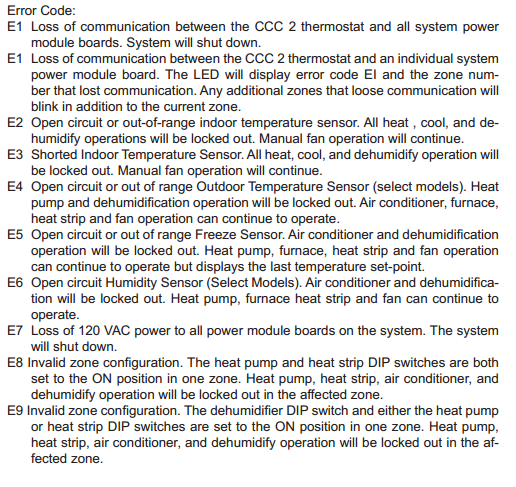
When the system determines that one of the faults listed below has occurred an error code will be displayed in the LCD.
| Error Codes | Solution |
|---|---|
| E1 | Loss of communication between the CCC 2 thermostat and all system power module boards. System will shut down. |
| E1 | Loss of communication between the CCC 2 thermostat and an individual system power module board. The LED will display error code EI and the zone num- ber that lost communication. Any additional zones that loose communication will blink in addition to the current zone. |
| E2 | Open circuit or out-of-range indoor temperature sensor. All heat , cool, and de- humidify operations will be locked out. Manual fan operation will continue. |
| E3 | Shorted Indoor Temperature Sensor. All heat, cool, and dehumidify operation will be locked out. Manual fan operation will continue. |
| E4 | Open circuit or out of range Outdoor Temperature Sensor (select models). Heat pump and dehumidification operation will be locked out. Air conditioner, furnace, heat strip and fan operation can continue to operate. |
| E5 | Open circuit or out of range Freeze Sensor. Air conditioner and dehumidification operation will be locked out. Heat pump, furnace, heat strip and fan operation can continue to operate but displays the last temperature set-point. |
| E6 | Open circuit Humidity Sensor (Select Models). Air conditioner and dehumidifica- tion will be locked out. Heat pump, furnace heat strip and fan can continue to operate. |
| E7 | Loss of 120 VAC power to all power module boards on the system. The system will shut down. |
| E8 | Invalid zone configuration. The heat pump and heat strip DIP switches are both set to the ON position in one zone. Heat pump, heat strip, air conditioner, and dehumidify operation will be locked out in the affected zone. |
| E9 | Invalid zone configuration. The dehumidifier DIP switch and either the heat pump or heat strip DIP switches are set to the ON position in one zone. Heat pump, heat strip, air conditioner, and dehumidify operation will be locked out in the af- fected zone. |
System Reset Procedure
When your unit was installed the appropriate dip switches on the electronic control board were turned on to match your system configuration. Any time these settings are changed, a system reset will need to be done before the CCC 2 thermostat will recognize the updated selection.
To do a system reset:
- Make sure the CCC 2 thermostat is in the OFF mode.
- Simultaneously press the MODE and ZONE buttons. The LCD will display “IniT” and all available zones.
- Release the MODE and ZONE buttons.
- Press the ON/OFF button to exit system set up.
Maintenance
Air Filter – Periodic cleaning or replacement of the air conditioner/heat pump air filters is required. When a system fan run time exceeds 1000 hours the filter icon is displayed in the LCD. See “Quick reference to LCD icons” on page 3. When this occurs wash the filter with soap and warm water. Let dry and reinstall. NEVER run the air conditioner without the air filter in place. This may plug the unit evaporator coil with dirt and substantially degrade the performance of the unit. To reset the fan run time and clear the filter icon, hold the INSIDE and OUTSIDE but- tons for three seconds. This will clear the fan run time for the current zone selected. Dometic CCC 2 thermostat: Clean the CCC 2 thermostat with a moist soft cloth. DO NOT spray water directly on the CCC 2 thermostat. DO NOT use solvents for cleaning.
Service
In the unlikely event the unit fails to operate or operates improperly, check the following before calling your service center.
- If your RV is connected to a motor generator, check to be sure the motor genera- tor is running and producing power.
- If the RV is connected to a power supply by a land line, check to be sure the line is sized properly to run air conditioner load and it is plugged into the power supply.
- Check your 120 VAC fuse or circuit breaker to see if it is open. Insure fuse is not burnt, or circuit breaker is ”ON” and not activated.
- Check your 12 VDC fuse or circuit breaker to see if it is open.
- After the above checks, call your local service center for further help. This unit must be serviced by qualified service personnel only.
When calling for service, always give the following:
- Unit Model Number and Serial Number found on Identification Label located on the Base Pan of unit bottom. It is necessary to remove the return air cover to expose the rating plate.
- Electronic Control Kit Part Number and Serial Number found on Identification Label located on the side of the Kit. This kit is mounted in the return air cavity and can be exposed by removing the return air cover.
Comments
Post a Comment