This air conditioning system meets strict safety and operating standards. As the installer or service person, it is an important part of your job to install or service the system so it operates safely and efficiently.
| Error codes | Faults and Solutions |
|---|---|
| E01 | Error receiving of serial communications signal. Remote controller is detecting unusual signal from indoor unit. |
| E02 | Error transmitting of serial communications signal. Remote controller is detecting unusual signal from indoor unit. |
| E03 | Indoor unit is detecting unusual signal from the remote controller or group control. |
| E08 | Indoor unit address setting is duplicated. Improper setting of indoor unit or remote controller. |
| E09 | Remote controller address (RCU.ADR) is duplicated. Improper setting of indoor unit or remote controller. |
| E11 | Error receiving of serial communications signal. Indoor unit is detecting unusual signal from signal option. |
| E14 | When using flexible combination control, main indoor unit address setting is duplicated. (judged by outdoor unit.) Improper setting of indoor unit or remote controller. |
| E04 | Error receiving of serial communications signal. Indoor unit is detecting unusual signal from outdoor unit. |
| E05 | Error transmitting of serial communications signal. Indoor unit is detecting unusual signal from outdoor unit. |
| E06 | Error receiving of serial communications signal. Outdoor unit is detecting unusual signal from indoor unit. |
| E07 | Error transmitting of serial communications signal. Outdoor unit is detecting unusual signal from indoor unit. |
| E15 | No. of judged indoor units or total capacity of indoor units is small. Auto. address setting is not correct. |
| E16 | No. of judged indoor units or total capacity of indoor units is large. Auto. address setting is not correct. |
| E18 | Error receiving of serial communications signal. Indoor unit is detecting unusual signal from another indoor unit. |
| L02 | Model setting of indoor unit is not matching the outdoor unit. Improper setting of indoor unit or remote controller. |
| L03 | When using group control, main indoor unit address setting is duplicated. Improper setting of indoor unit or remote controller. |
| L07 | Improper wiring between indoor units. Improper setting of indoor unit or remote controller. |
| L09 | Capacity code of indoor unit is not set. Improper setting of indoor unit or remote controller. |
| L11 | Improper wiring of group control wiring. Improper setting of indoor unit or remote controller. |
| P09 | Improper wiring connections of ceiling panel. |
| P01 | Thermal protector in indoor fan motor is activated. Protective device in indoor unit is activated. |
| P10 | Float switch is activated. Protective device in indoor unit is activated. |
| P02 | Thermal protector in outdoor fan motor is activated. Protective device in outdoor unit is activated. |
| P03 | Discharge gas temperature of PC comp. is unusual. Protective device in outdoor unit is activated. |
| P04 | High pressure switch is activated. Protective device in outdoor unit is activated. |
| P05 | Negative phase or voltage drops. Protective device in outdoor unit is activated. |
| P31 | Other indooor unit is warning. Protective device in outdoor unit is activated. |
| F01 | Indoor coil temp. (E1 = TH2) cannot be detected. Indoor thermistor is either open or short. |
| F02 | Indoor coil temp. (E2 = TH3) cannot be detected. Indoor thermistor is either open or short. |
| F10 | Indoor room temperature cannot be detected. Indoor thermistor is either open or short. |
| F04 | Discharge gas temp.A can not be detected. Outdoor thermistor is either open or short. |
| F06 | Outdoor coil liquid temp. (C1 = TH0E) cannot be detected. Outdoor thermistor is either open or short. |
| F07 | Outdoor coil gas temp. (C2 = TH0C) cannot be detected. Outdoor thermistor is either open or short. |
| H01 | PC compressor motor is overloaded. Protective device for compressor is activated. |
| H02 | PC compressor motor is locked. Protective device for compressor is activated. |
| H03 | Compressor current detection circuit is defective. Protective device for compressor is activated. |
| H06 | Low-pressure protector is activated. Protective device for compressor is activated. |
| H18 | Standard comp. contactor (Mg SW) is chattering. Protective device for compressor is activated. |
N.B.: In the event of other error codes, contact a qualified technician for assistance.
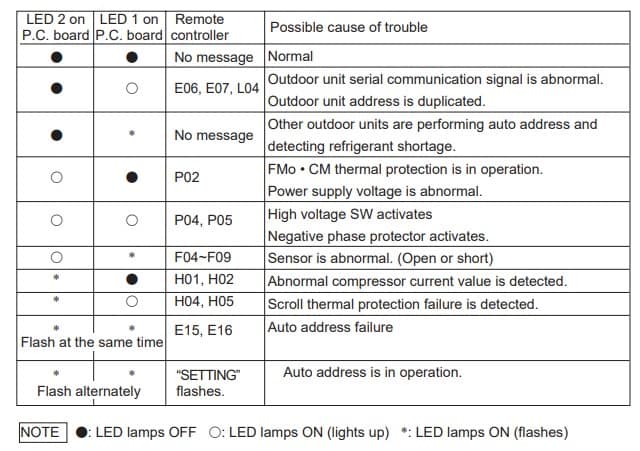
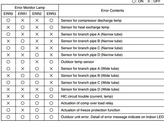
LED Indication on the Outdoor Unit’s P.C.B. Ass’y:
If something goes wrong with the outdoor unit, LED lamps on the outdoor P.C.B. Ass’y light up to show the cause of the trouble, in addition to the Alarm message on the remote controller.
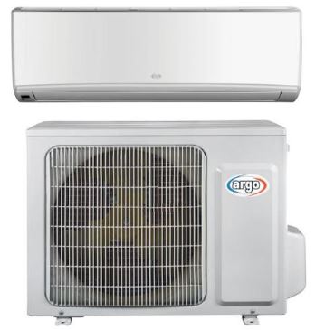
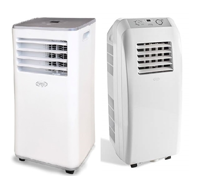
Argo AC Troubleshooting
Possible faults and solutions:
Do not attempt to repair the unit yourself. Improper repair can cause electric shocks or fire. Disconnect the unit from the power supply before contacting your local Technical Service Centre. Carry out the following checks before contacting your Technical Service Centre:
Fault: The indoor unit does not receive the signal from remote control or the remote control does not seem to be working
Check:
- Is there noticeable interference (e.g. static electricity, stable voltage)?
- Is the remote control within the signal reception range? Are there any obstacles between the remote control and the receiver?
- Is the remote control pointed at the receiver?
- Is the remote control’s sensitivity low? Are icons blurred or missing?
- Do icons fail to appear on the display when you operate the remote control?
- Is there a fluorescent light in the room?
Solution:
- Pull out the plug. After about 3 minutes reinsert the plug and restart the unit.
- The maximum signal reception distance is 8 m. The remote control will not work beyond this distance. Remove the obstacles.
- Point the remote control at the receiver on the indoor unit.
- Check the batteries. If the batteries are very low, replace them.
- Check if the remote control is damaged. If it is, replace it.
- Position the remote control next to the indoor unit. Turn off the fluorescent light and try again.

Fault: No air comes out of the indoor unit
Check:
- Is the indoor unit’s air inlet or outlet blocked?
- In heat mode, has the indoor temperature reached the set temperature?
- Has heat mode only recently been selected?
Solution:
- Remove the obstruction.
- Once the set temperature has been reached, the indoor unit will stop blowing out air.
- To prevent blasts of cold air from being blown out, there will be a delay of several minutes before operation begins (this is normal).
Fault: The air conditioner is not working
Check:
- Is there a power cut?
- Has the plug come loose?
- Has the circuit breaker tripped or has the fuse blown?
- Is the wiring faulty?
- Was the unit restarted immediately after shutdown?
- Is the setting on the remote control correct?
Solution:
- Wait for the power to be restored.
- Reinsert the plug
- Have the circuit breaker or fuse replaced by a qualified technician.
- Have it replaced by a qualified technician.
- Wait 3 minutes and then restart the unit.
- Reset the function.
Comments
Post a Comment