Single Zone Mini-Split Inverter System Error Codes:
| Error Codes | Solution |
|---|---|
| E5 | AC over current protection. Restart the unit. If the error does not clear, contact your dealer or qualified service technician. |
| E8 | High temperature protection. Restart the unit. If the error does not clear, contact your dealer or qualified service technician. |
| H4 | High temperature protection. Restart the unit. If the error does not clear, contact your dealer or qualified service technician. |
| H6 | Indoor fan motor error. Restart the unit. If the error does not clear, contact your dealer or qualified service technician. |
| C5 | Jumper cap malfunction protection. Contact your dealer or qualified service technician. |
| F1 | Indoor ambient sensor open or short circuit. Contact your dealer or qualified service technician. |
| F2 | Indoor tube sensor open or short circuit. Contact your dealer or qualified service technician. |
If other error codes are present, contact your dealer or qualified service technician.
If any of the following occurs, shut off the unit and contact your dealer or qualified service technician:
- Power cord overheats or becomes damaged
- If you notice a burning smell
- The unit trips the breaker panel or cycles off frequently without obtaining the set temperature
- Abnormal sound during operation
- If you notice water leakage
Troubleshooting
Condition: Unit doesn’t run
- When unit is started immediately after it is just turned off
- When power is turned on
Possible Reason:
- Overload protection switch delays unit start up for three minutes
- The unit is in standby for one minute
Condition: Mist comes from the unit. When cooling cycle starts
Possible Reason: Indoor high humidity air is cooled rapidly
Condition: Sound comes from the unit
- Slight cracking sound is heard when unit starts
- There is sound when cooling
- There is sound when unit starts or stops
- There is slight sound when unit is running or after running
- Cracking sound is heard when unit is operating and after operating
Possible Reason:
- This sound occurs when the electronic expansion valve initializes.
- The sound of gas refrigerant flowing in unit
- This sound occurs when gas refrigerant starts or stops flowing
- The sound of the drainage system operating
- This sound occurs when the unit panels expand or contract due to temperature change
Condition: The unit blows out dust. When the unit has been off for a period of time.
Possible Reason: Dust in indoor unit is blown out
Condition: The unit emits odor. When the unit is operating
Possible Reason: The room odor absorbed by the unit is blown out again
Condition: Indoor unit still runs after switch off. After every indoor unit receives the “stop” signal, fan will keep running
Possible Reason: Indoor fan motor will keep running 20-70 seconds to use excess cooling and heating and prepare for the next operation
Condition: Mode conflict. COOL or HEAT mode can not be operated.
Possible Reason: When the indoor operating mode conflicts with that of the outdoor unit, the indoor fault indicator will flash and conflict will be shown on the wired controller after 5 minutes. Indoor unit stops running and the outdoor unit changes its mode of operation to match the indoor unit, then the unit will go back to normal. COOL mode doesn’t conflict with DRY mode. FAN mode doesn’t conflict with any mode.
NOTE: If the problem persists after checking the above items and taking appropriate measures, please stop operation of the unit immediately and contact your local service agency or dealer. Diagnostics and repairs should be completed by a professional service technician.
Auxiliary Operation
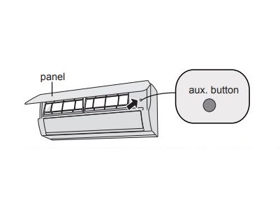
If the remote controller is lost or damaged, please use the auxiliary button to turn on or turn off the air conditioner. Open the front panel of the unit and press the aux. button to turn on or turn off the unit. When the unit is operated by the auxilliary button it will run only in auto mode.
Note: Auto mode operation – 77°F is the set temperature for cooling operation and 68°F is the set temperature for heating operation. There is no adjustment available for auto mode operation.
Indoor Unit Maintenance
- Clean the outer surface of the unit with a dry or damp cloth.
- If there is residue, the unit may be cleaned with a mild detergent solution. Do not use chemical solvents or flammable liquids to clean the surface of the unit. Wipe dry after cleaning with a soft dry cloth.
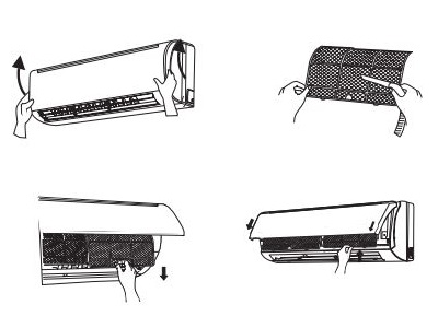
- Clean the filter a minimum of every three months. Clean more often if it is in an area that is dusty or smoky.
- Open the front outer panel of the indoor unit.
- Remove the filter by grasping the edges and pulling downward.
- Clean the filter using a vacuum or rinse under cool, clear water.
- If the filter is very dirty, use warm water (below 115°F/ 45°C). A mild detergent should only be used if the residue cannot be removed with warm water. Rinse the filter thoroughly before allowing to air dry. If the filter cannot be adequately cleaned, contact your dealer for a replacement filter.
- Let the filter air dry to avoid warping. Do not dry the filter in direct sunlight.
- Reinstall the filter into the clips and close the front panel.
Comments
Post a Comment